
ChipSHOUTER Setup & Operational Guide
1. Hardware Connections
-
Probe Tip: Install ONLY the 1mm Red Injection Probe Tip onto the SMA Saver port located on the front panel.
⚠️ Important: Never rotate the center pin during installation—spin only the outer connector nut to secure it.
-
Power Connection: Plug the provided 19V DC power adapter into the DC power jack.
-
PC Connection: Connect the RJ12 expansion cable from the ChipSHOUTER to the Isolated USB Adapter, then connect the adapter to the PC using the micro-USB cable.
2. Driver & Software Setup
-
Driver Configuration: No driver installation is required. The system uses the standard FTDI drivers already present on your system for CmdFlash. The PC will recognize the device automatically upon connection.
-
Software Management: All control, configuration, and interface operations are handled directly through the CmdFlash proprietary panel. No external serial terminal or software is required.
3. Operational Workflow
-
Automated Operation: The entire execution process (arming, pulse injection, fault timing, and disarming) is fully managed in the background by CmdFlash.
-
Manual Interventions: None required. Do not press any physical buttons (ARM/PULSE) on the ChipSHOUTER hardware during the procedure, as CmdFlash handles the sequence automatically.
⚠️ Safety Warning: High voltage and strong electromagnetic pulses are generated during operation. Keep hands and conductive tools away from the 1mm red probe tip while the system is powered and connected to CmdFlash.
ECU Positioning & Frame Setup
1. Frame & Mount Assembly
-
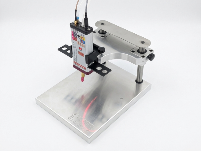
Positioning Frame: Use any standard positioning frame previously utilized for BDM (e.g., EDC16 protocols) equipped with a standard probe attachment. (If needed, contact the sales department to purchase one).
-
ChipSHOUTER Plastic Support: Secure the dedicated plastic holder (not included in the standard kit) to the frame.
💡 Note: You can purchase the support from the official shop, order it through sales, or download the free 3D-printing project file to print it locally with no shipping costs or delay. ChipSHOUTER HOLDER (3D PRINTER .stl)
💡 Note: You will need two small pieces of adhesive felt (20x20x2.5 mm) to stick inside the mount; this allows the tool to slide smoothly and makes positioning much easier
2. Connections & Wiring
-
ECU Power & Boot: Connect the CmdFlash BOOT Interface and the main power supply leads directly to the front connector of the ECU.
-
RF Output Cables: Mount the SMA Adapter onto CmdFlash and connect the SMA-to-SMB cable directly to the ChipSHOUTER.
3. Alignment & Probe Placement
-
Target Masking: Place the specific alignment mask (included in the kit) over the target processor.
-
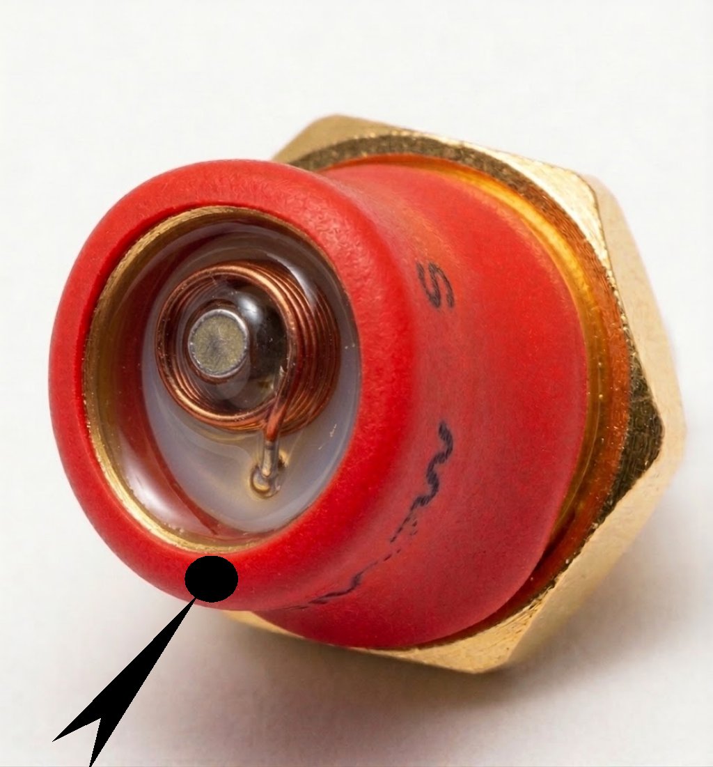
Probe Positioning: Gently lower the ChipSHOUTER until the 1mm Red Probe Tip rests softly in the center of the opening on the mask. Please be advised that the internal metallic core may not always be perfectly centered relative to the copper winding and the heat-shrink tubing. Due to these slight alignment variations, achieving consistent precision during the unlocking/release operation can sometimes be challenging.To prevent any inconsistencies, we recommend marking the outer heat-shrink tubing directly opposite the core position using a marker pen (as illustrated in the attached image). When mounting the tip, align it so that this mark faces directly toward the operator.
-
Reset Pin Connection (Optional): Connect the auxiliary probe tip to the RST pin as indicated in the Help manual (optional, but strongly recommended for higher success rates). The contact tip to be routed to the reset pad must be connected to the spring connector on the glitch board marked with RST. Do NOT use the Reset line from the bench wiring.
4. Software Execution
-
Identification & Unlock: Launch the identification and unlock procedures using the standard buttons inside the CmdFlash application.
-
Dedicated Control Panel: Once initiated, a new specialized panel will automatically pop up on your screen. This window will guide and manage all ChipSHOUTER parameters, as covered in the next section.
ChipSHOUTER Control Panel Overview
The ChipSHOUTER panel is the integrated monitoring and control interface within the CmdFlash software. Under standard operating conditions, the panel opens and closes automatically as required by the routine. It serves primarily as a real-time visual status indicator and generally requires no manual intervention from the operator.
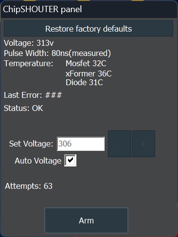
Below is the detailed breakdown of the functions and status indicators:
1. Restore Factory Defaults
-
Function: Resets all ChipSHOUTER parameters back to their original factory settings.
-
Usage: Recommended during the first initial setup, or if the device was previously used with other third-party software or tools.
2. Status Indicators & Telemetry
The central section provides real-time telemetry from the hardware:
-
Voltage & Pulse Width: Displays current voltage and measured pulse duration (e.g.,
80ns). -
Temperature: Live thermal monitoring of critical internal components:
-
MOSFET
-
xFormer (Transformer)
-
Diode
-
-
Status, Last Error & Attempts: Shows operational status (e.g., OK), error log codes, and the pulse attempt counter.
3. Pulse Voltage Management (Set Voltage / Auto Voltage)
-
Auto Voltage (Default): Kept checked by default so CmdFlash automatically manages the ideal injection voltage.
-
+/-Buttons (Manual Adjustment): Allows manual override of the output voltage (Set Voltage).⚠️ Note: Manual adjustment is intended only for special edge cases and requires an experienced operator. For standard procedures, keep Auto Voltage enabled.
4. Manual Arming (Arm Button)
-
Function: Manually arms the ChipSHOUTER hardware.
-
Usage: Arming is typically handled automatically by CmdFlash. However, on rare occasions, strong electromagnetic pulses (EMP) generated by the device itself may desynchronize the hardware.
-
Recovery: If manual re-arming is ever required, the CmdFlash software will provide step-by-step on-screen instructions to guide you through it.
Safety Precautions & Operating Recommendations
To ensure reliable performance, prevent hardware damage, and avoid bricking control units during the unlock sequence, strictly adhere to the following guidelines:
1. Active Cooling System (Do's and Don'ts)
The ChipSHOUTER generates significant heat during continuous pulse sequences. Proper cooling setup is critical:
-
Manual Reference: For complete technical specifications regarding the active cooling system, please consult the official ChipSHOUTER User Manual.
-
Always Connect Air Cooling: Ensure the active air cooling supply is properly attached to the device before starting high-frequency or extended pulsing sessions.
-
Avoid Excessive Air Pressure: Do not use high-pressure compressed air lines (e.g., unfiltered industrial air lines without a regulator). Excessive pressure can damage internal components or dislodge thermal sensors. Use low-pressure, regulated clean air as specified.
-
Overheating Risks: Operating the device without cooling—or with blocked airflow—will trigger thermal protection faults (
MOSFET/xFormer/Diodehigh temp), leading to premature shutdown, missed fault-injection windows, or potential long-term hardware degradation.
2. Target Mask Alignment & Processor Verification
-
Processor Matching: Before placing the mask, double-check that the alignment mask version matches the exact processor model mounted on the target ECU.
-
Pin 1 / Index Alignment: Ensure the alignment dot (index mark) on the plastic mask is 100% aligned with the physical dot/corner mark on the target processor chip.
-
Precision Placement: Incorrect mask orientation or offset will cause the 1mm probe tip to inject electromagnetic pulses into the wrong chip area, resulting in failed unlock attempts.
3. Power Supply & UPS Recommendation
-
Original Power Adapters Only: Use only the original, factory-supplied power adapter included in the ChipSHOUTER kit (19V DC).
-
CmdFlash Power Requirements: Likewise, powering the CmdFlash tool must be done exclusively with the official power supply as detailed in the CmdFlash Help documentation. Do not use third-party or generic power supplies, as voltage ripple can disrupt precision timing.
-
Uninterruptible Power Supply (UPS) Mandatory Recommendation: It is strongly recommended to connect the entire setup (PC, CmdFlash, and ChipSHOUTER) to a reliable UPS (Uninterruptible Power Supply).
⚠️ Warning: If power drops or fluctuates while CmdFlash is updating the ECU bootloader to apply the security patch, the processor will suffer an incomplete flash write, rendering the ECU permanently unbootable ("bricked").